A Masthead Antenna Compass
By Paul McMahon VK3DIP
Back
Home
As appeared in NERG NEWS September / October 2021
Source Etc.
Masthead PIC Source code and Binary
PC Board Artwork in Sprint Layout Format
Part 1 - Hardware
Antenna rotators are an invaluable Ham resource and, apart from being a bit costly for good new ones, they are on the whole at least mechanically pretty reliable. One problem they do have however is the mechanism used to indicate the position. The most complicated and common scheme, particularly for larger rotators, uses a variable resistor and a metering circuit. Smaller cheaper rotators tend to use dead reckoning based on time and synchronous ac motors. Whichever mechanism is used there is a tendency to become less accurate over time, either due to worn or corroded resistors, or in the case of the dead reckoning due to accumulated errors over the period of a couple of beam positionings.
These position issues tend to be more of a problem if like me you tend to have second hand rotators.
Reconditioning old rotators has been the focus of several NERG DIY gatherings at the clubrooms, but there comes a point when the variable resistor has just totally worn out and often getting replacements can be problematic.
This project is for those cases, or where you are sick of having to constantly recalibrate the dead reckoning type of rotator.
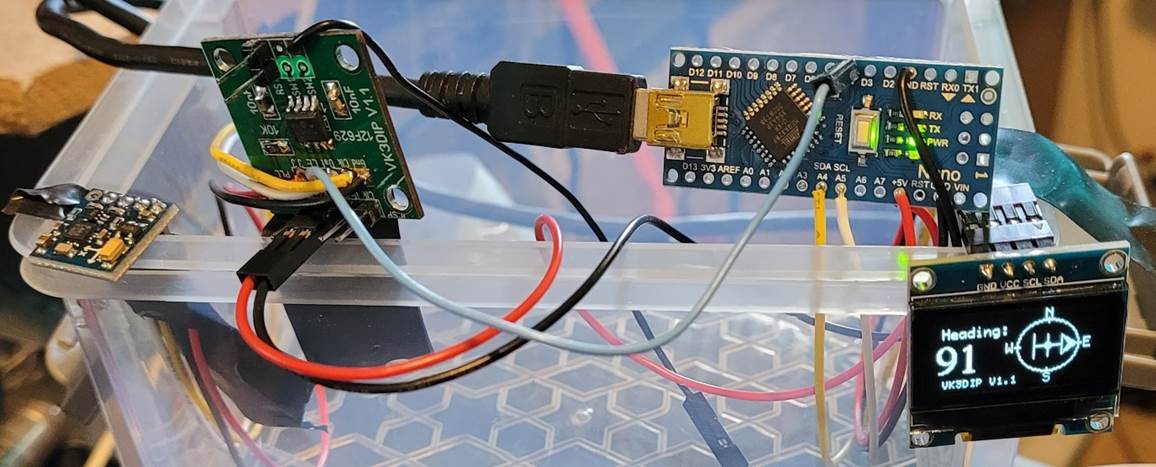
Figure 1- Initial Test Setup
Figure 1 shows the initial hookup I used to test out ideas. From left to right It consists of a HMC5883L hall effect magnetic field sensor, a 12F629 PIC to talk to the sensor and forward the results to the Arduino Nano, which in turn displays the result on an OLED graphics display.
The HMC5883L sensor used here comes on a small module available from the usual ebay/Aliexpress sources for about $4 each, just search for GY-271 and you will find lots.
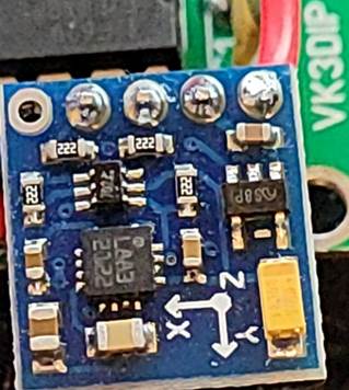
Figure 2 - GY271 module.
I picked this module because the HMC5883L magnetic field sensor chip (the square chip marked L883 in Figure 2) is a 3.3V component and my other logic is 5V. The GY-271 also has a 3.3V low dropout regulator (the chip marked 5 8P should be such, but in the case of two of these modules I got it was incorrectly a 5V regulator which made things hot and stop working), and a pair of mosfets setup as 5V/3.3V level converters (the small 6 legged chip) for the I2C communications. It is worthwhile checking the regulator if you get one of these and making sure it is 3.3V, as I don’t know how common this particular issue is. The simplest way to do this is to very briefly apply power to the 5v VCC pin of the board and measure the regulator output voltage, the positive striped end of the yellow tantalum capacitor is a convenient spot. If it is not 3.3V, as in the case of at least two of mine, the HMC5883 was not permanently damaged , and replacing the regulator with a known 3.3V one bought everything back to life.
While talking about problems with these modules I should also mention on one of the other versions I obtained the regulator was correct but the main chip rather than being a HMC5883L was instead a QMC5883 (marked DA5883). The QMC5883 is actually an improved second source version of a HMC5883L however while it is hardware wise pin compatible, software wise it is slightly different so you need to use a different I2C address, and some of the registers are different. With those minor software changes it should actually work better than the HMC5883L as it is automatically thermally compensated and has more resolution in its measurements. So despite what some sources say on the web these are not fake, just not what you may have been expecting, the wrong regulator is actually a worse problem.
Whichever main chip is used, these devices in my case measure the various components of the earths magnetic field and using a bit of mathematics allow calculation of the way the PCB is oriented. While talking about those measurements we should note that the sensor is actually a three axis magnetometer, ie. it provides three orthogonal (X backwards/forwards, Y left/right, and Z up/down) field measurements. The orientation of these axis is marked on the module PCB. In my case I use the board flat ie. the Z axis value should be constant, and I only use the X and Y values, but if you wanted to say also get an elevation/tilt bearing a bit more trigonometry with the Z and X values would provide that.
As mentioned above, both the HMC5883L and the QMC5883 interface via an I2C protocol, and I2C only works reliably over relatively short distances thus the 12F629 close to the sensor up the masthead to query the sensor via I2C and to then send via standard serial down the mast to the base processor (the Nano) and attached display. Standard RS232 serial, especially if it is the pseudo RS232 TTL 5V level version, is also practically limited to distances of a meter or so, for the distances likely to be involved here between mast top and shack we need to use something else. I initially thought of some form of wireless setup, but that has the twin problems of how to power it, and how to make it reliable in the high RF environment close to antennas. I ended up sticking with a wired approach using a pair of RS485 modules (about $3 each from ebay etc.). These modules convert between TTL level RS232 to RS485 levels. RS485 uses differential signalling and is specified for long runs , at high speeds , and electrically noisy environments. The spec says that they should be able to provide reliable comms at up to 1.2KM at 100KBPS which should be more than adequate for this use here.
I initially intended to only use a single small OLED display so it could be more easily incorporated into existing rotator controller boxes, (ebay etc. search SSD1306 128x64 ~$5-$6) however these displays especially if you put a lot of detail on them can be relatively slow. In the test setup shown in Figure 1, where I went mad with detail, it took the best part of one second to draw the whole screen, which meant correspondingly less time to handle the (software) serial stream down from the masthead sensor without buffer overruns. So much so I had to take the bit rate coming down from the masthead down to 300BPS. While probably liveable with for this application, it did mean there was noticeable lag in the display, and it did jump around a lot. I did try one or two things to speed up the display but ended up just adding another standard 16 char 2-line LCD display to show the numerical bearing and restricting the graphical display to just the graphics of the rotating beam. This separation of duties enabled me to considerably reduce the display time such that 1200BPS was now very reliable with now multiple data updates per second.
The final circuits I ended up with are shown below in Figure 3, and Figure 4. These two sections are connected via a length of CAT5 or equivalent four twisted pair cable (I actually used CAT3 because I got a drum of it cheap from the tip shop). I used one twisted pair (Blue/BlueWhite, Blue to B, BlueWhite to A) for the differential serial data, and the other six conductors, three in parallel for +12 (Orange, OrangeWhite, and BrownWhite) and three in parallel for earth/ground(Green, GreenWhite, and Brown).
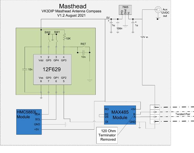
Figure 3- Masthead Section
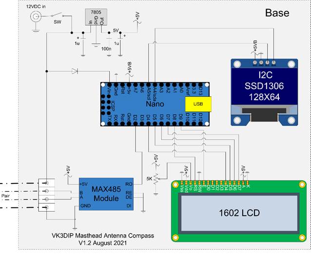
Figure 4- Base Section
The MAX485 modules (the main IC that does the work of converting TTL to RS485 is the Maxim MAX485,) at the masthead and base started out identical. In this unidirectional use however one is always the transmitter and the other the receiver. The receiver end (base) module is hardwired into receive only mode with RE or Receive Enable inverted, and DE Driver (Transmit) Enable connected together and to ground (low). The transmitter end (masthead) is hardwired to Driver mode , DE connected to RE and the pair left for the onboard pull ups to take them high. In my case I also modified only the masthead MAX485 module by removing the onboard 120 Ohm terminating resistor. For my MAX485 boards this was marked as R7 (see Figure 5). You only need this termination at the RX end, and having it at the TX end effectively doubles the power needed to come from the masthead regulator and MAX485 chip. As you can see I also put a heatsink on the LM7805 as well, even with the terminator removed it still gets warm.
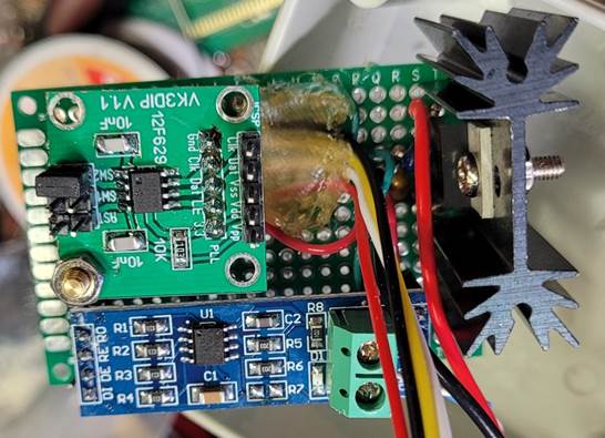
Figure 5 - Masthead Hardware.
The 12F629 is a surface mount version on an update of the small board I used for the ADF4350 programming in my 2.4GHz transverter, and Signal generator mixer. The 12F629 software (to be discussed in part 2) reads the values from the two jumpers and sets the BPS rate down to the base accordingly. SW2 only as shown gives 1200 BPS. The 12F629 and MAX485 Modules, as well as the LM7805 regulator are mounted on a small generic protoboard to give mechanical stability. Note the hot melt glue acting as strain relief on the four wires going off to the dupont connector for attaching to the HMC5883L sensor on the lid of the box. This is necessary as the fine gauge cores of these wires don’t take many flexes before breaking.
The Masthead end is mounted in a small waterproof 3”x3”x2” electrical junction box with the HMC5883L attached to the lid with a small dob of neutral silastic. (Figure 6) Note the arrow drawn on the inside which lines up with a matching arrow on the outside, and the X (North or 0 degrees) axis shown on the HMC5883L board. The various CAT 5 wires from the base are terminated on screw connectors which in the case of the 12V may have other wires connected to if you need a source of always on power up the mast for preamps etc.
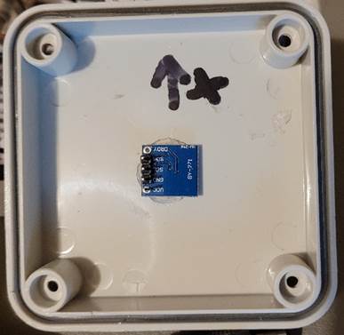
Figure 6- GY271 on inside of lid.
Figure 7 shows the complete Masthead component mounted in its waterproof box. The box is bolted (using brass bolts to minimise magnetic interference) to a piece of Perspex which in turn has a u-bolt and V bracket (as far away as possible) attached to affix to the stub mast above the rotator and below the beams. The Arrow on top of the box is aligned with the X axis of the sensor as mentioned above. If you want to reference things to magnetic north this arrow should be exactly aligned with the antenna boom. Once done if the display says 0 degrees then the beam is pointed at magnetic north. If you want true north then you need to allow for the magnetic declination which varies from place to place. For much of Melbourne this amounts to some 11 degrees 50 minutes (east), but for the Otway’s where I contest from, this is 11 degrees 27 minutes (east). There are various sites on the web where you can look up these values if you want to be really precise. A simple way to be good enough, is to point your beam where you believe true north to be then move the sensor around the mast until the display reads 0. Around here the angular difference between the antenna boom and the arrow should be end up at around 11 -12 degrees. This would work with any known heading if you knew from say some contesting software that the bearing from Your QTH to another station was 100 degrees then you could peak the beam on them and then move/rotate the sensor around the stub mast until the display showed 100 and then fix it in place.
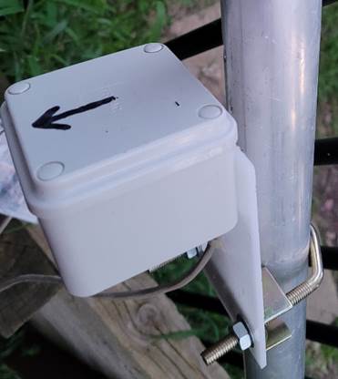
Figure 7- Completed Masthead Section
You also of course could just do the beam and arrow alignment as in the magnetic north version and numerically add/subtract the declination in your head/software.
Figure 8, and Figure 9, show the construction of the base unit. As we were/are in lockdown and couldn’t get to Jaycar (and I didn’t fancy mail ordering a single jiffy box) I used a small $2 clip top container from the local version of a $2 shop. This container apart from being available, also has the advantage of being clear, particularly the lid, so I could just mount the displays to the back of the lid without having to cut square holes and they are perfectly visible.
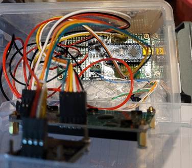
Figure 8 - Inside the Base
As in the masthead component, I again mounted the modules on a protoboard used as a motherboard. In this case I used a protoboard I had designed specifically for an Arduino Nano, as well as suiting the Nano, the board has specific pads for the LM7805. In the base case, current drain for the receiver version of the MAX485 and the displays etc. is considerably less than the masthead case so no heatsink is required.
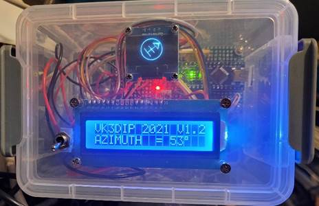
Figure 9 - Base in $2 Clip Top Box.
The protoboard motherboard also has room for a 5K ohm trim pot to adjust the 16x2 LCD contrast. Once again hot melt glue is used for dupont connector wires strain relief. Note, that while I did put in an 1N4004 power diode between the switched 12 V and the Nano Vin for isolation, this is not 100% effective. If you just plug in a cable to a PC USB port to the Nano and even with the 12V off, the 5V from the high lines on the Nano logic ports connected to the LCD, can come back through the LCD on chip protection diodes and get to the otherwise unpowered 5V line and partially power the rest of the base. Putting any amount of power through these protection diodes is not a good thing so if you want to connect the Nano via USB to the PC, either have the rest of the power on, or if you just want to reflash the Nano, take it out of the socket on the Motherboard first. The base unit with the current version of the software also sends out the calculated heading as well as the X,Y,Z values received from the sensor at 19.2KBPS via USB to the PC for debugging or use with any other software etc.
Part 2 – The Software - By Paul McMahon VK3DIP
A Quick Recap.
Last time I went through the hardware side of the project , this time I will concentrate on the software. There is one further hardware thing however I should touch on first. Since building the prototype of this compass I have ordered and received several more of the GY271 compass modules. So far, while there have been a couple (perhaps someone’s old stock) with the original Honeywell HMC5883L chip (see Figure 1), perhaps not surprisingly as I believe the Honeywell part has been discontinued, the majority of new GY271 modules I have got have been using the newer not discontinued OSOYOO QMC5883L chip (see Figure 2). Luckily there have been no more with the incorrect 3.3V regulator so perhaps that problem has been fixed.
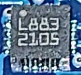 Figure 1- Closeup of HMC5883L
 Figure
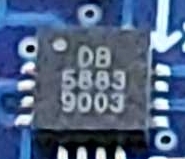
2 -Closeup of QMC5883L
Figure
2 -Closeup of QMC5883L
Note, the Dx code (DB on the example above) could be DA, DB, DC, etc with the x intended to indicate versions produced for particular customers. So far I have seen DA’s and DB’s both seem to work identically as far as I can see. The last 4 digits in both cases are just a batch or date code and as far as I know are not relevant.
You do have to look closely at the chips because from a distance the GY271’s look pretty similar (see Figure 3)
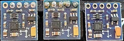
Figure 3- Left to Right, HMC5883L and two different QMC5883L's
As I now have mostly QMC based versions and as the QMC is in many ways a better chip, I decided to update the HMC only masthead code I used in the prototype to be able to handle either chip (with a jumper setting) and it is that code that the following describes.
Note, the QMC5883L offers much higher resolution measurements(16-bit ADC vs 12,) speed 200Hz data refresh vs 75Hz, 512 times averaging vs 8 , and lastly is automatically temperature compensated.
Masthead Code
There are actually two bits of software in this project that must work together. The PIC code in the masthead component to talk to / query the compass module and send data down the line, and the Arduino Nano code in the base unit to receive that data, interpret it and then display it to the human.
The first bit of code to talk about then is that for the PIC masthead. As this is actually only a relatively small amount of functionality and code space is quite limited in the 12F629 I wanted to keep the footprint here as small as possible, I could have just coded it directly in PIC machine code but I find that relatively difficult to understand what I was trying to do some years later. Conversely using the free Microchip IDE and compilers is way more powerful than is needed here. So similarly to the projects where I first used this 12F629 board, I ended up using the Oshonsoft PIC Basic compiler for this.
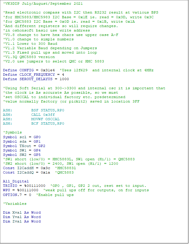
Figure 4 - PIC Code part 1
Figure 4 is the initialization section of the masthead code. As indicated in the comments as I am using software serial here and the 12F629 is free running, ie. not using a crystal oscillator. It is important that the internal RC clock is as accurate as possible.
Due to manufacturing differences if left uncalibrated each 12F629 will tend to free run at slightly different speeds, so to get some predictability these PIC components are calibrated at the factory and a chip specific “calibration” factor is measured and loaded into each chips flash memory. If this oscillation calibration factor is loaded into the chip OSCAL register at start up then the internal clock will run at a reasonably accurate 4MHz. In a bit of cheap fudge the factory OSCAL value is stored as the last couple of bytes in the Flash program memory and not automatically loaded into OSCAL. This presents two possible problems. Firstly, it is up to person writing the code to read that cal value and load it into OSCAL and if you don’t do it the PIC internal oscillator will be at some frequency most likely some distance away from 4MHz. Often this doesn’t matter (such as in the I2C talking to the PLL in my previous 12F629 projects) and this step can be left out, but with software serial that we want to be able to reliably read down at the base, this accuracy is vital. Secondly it is easy if your PIC programmer/ burner software is not aware of this fudge, to overwrite this cal factor with program code, or erase it, and then you must somehow redo the factory calibration to recalculate this value. Luckily if like me you use a Pickit 2 (or clone) programmer and software, it is both, aware of this fudge so it looks after it for you, plus if you do loose the calibration, it has a built-in tool that can recreate it and resave it in flash.
Anyway the four inline assembler (ASM: ) statements assume this cal value is present and read this from the flash memory and place it in the OSCAL register.
The constants I2CaddH and Q contain the write address for the HMC5883L, and QMC5883 respectively. There are also differences with the setting of the registers etc. as you will see latter.
You will note that to enable the weak pull ups on the GP4 and GP5 inputs (so we can just use simple shorting links to deck for configuration jumpers) we have to both set the WPU register for the individual pins using: “WPU = %00111000”
And we must also turn all weak pull ups on via the ![]() (bit 7) of the OPTION register (the
bar makes it active low so 0 is on) the line: “OPTION.7
= 0” Does this.
(bit 7) of the OPTION register (the
bar makes it active low so 0 is on) the line: “OPTION.7
= 0” Does this.
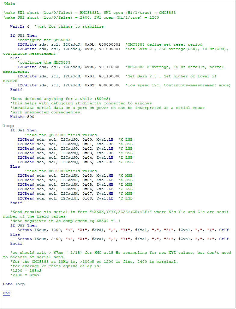
Figure 5 - Masthead Code Part 2
The remainder of the masthead code (Figure 5) firstly configures the sensor , and then goes into an infinite loop where it reads the measured X,Y, and Z, components of the magnetic field, and then sends the X,Y,Z values serially down the line to the base. The speeds and sensor chip type are set via SW1 and SW2 jumpers as per Table 1.
The setup for the QMC5883L and HMC5883L are different and not just in which registers they are set in.
In the HMC case I use a 15Hz refresh rate with 8 times oversampling/averaging. This is a playing safe configuration, the HMC5883L can work faster but the averaging is at maximum. Basically, we are going for as smooth a value as possible at a rate that would easily handle typical rotator speeds. I also set the gain (equivalent to the full scale reading of the HMC’s 12-bit ADC) to ±2.5Gauss. this is higher than strictly needed (typically the earth’s magnetic field maximum is about 0.65 Gauss) we could set it at the lower ranges of ±1.9, ±1.3, or even ±0.88 Gauss and get correspondingly more precision with the calculated bearing, but sticking midrange with this value gives enough precision to get one degree heading accuracy, and means we don’t have to mess with floating point bearing values. It is rarely necessary for ham purposes to have the bearing at fractions of a degree. Even very good rotators with a larger beam will flex in the wind by a degree or so, thus any higher resolution range seems a waste.
Note, in just the earth’s natural magnetic field the X,Y,Z values measured will indicate from about -0.65 to +0.65 Gauss depending on the actual orientation of the sensor in the magnetic field. This value is read by the HMC 12-bit ADC with a +2047 to -2047 (decimal) range. Each of those extremes represent the range value as set in the HMC5883L in my case 2.5 Gauss. I.e. +2047 would mean +2.5 and -2047 is -2.5 Gauss. Similarly a value of 0.65 Gauss would have a value of about hex 0x214 or 532 decimal. These results are represented by and retrieved as a 16 bit 2’s complement integer. Negative values in 2’s complement are most significant bit 1 other bits inverted so -532 decimal (-0.65 Gauss) would come out as a 16 bit 2’s complement of hex 0xFACD or unsigned decimal of 64205. Luckily the Arduino we are sending these values to, also has its standard INT data type as a 16bit 2’s complement so no actual conversion is required, and we can leave it all to the various compilers to just handle it.
In the QMC case I set the refresh rate to 10Hz, and 256 times oversampling/averaging. This is the slowest rate the QMC offers, and second highest averaging. Again this is trying to get a reasonably balanced smooth output without using the very high speeds (200Hz) and 512 times averaging the QMC is capable of, which the data sheet warns can lead to excessive power dissipation. I also set the gain (the maximum value in this case of a 16bit ADC) to ±2.0 Gauss which is less than the HMC case but which actually provides considerably higher resolution due to the 16-bit ADC as opposed to 12-bit case for the HMC. Like the HMC case the results are stored/retrieved as 16-bit two’s complement but in the QMC case the full 16-bit resolution is used.
There are a number of different values you could set either sensor up to depending on your specific requirements, the data sheets are your friends. Hopefully this code shows you how this would be done. One caution however, as already mentioned the different registers in the HMC and QMC chips are quite different and do very different things , writing the wrong thing ,to the wrong place, on the wrong chip, could produce very strange results and in the worst case damage the sensor by putting it into some high power test etc. mode for extended times and cooking it.
The code then reads the field values from the relevant sensor registers (HMC or QMC depending on SW1)
The rest of the code is, depending on the settings of the second jumper (see Table 1), basically a single line that sends the ASCII representation of the (unsigned) decimal values of the read X,Y,and Z field components to the base. The format of this consists of a less than (<) symbol as a start character followed by the three as read (unsigned) decimal field values (X,Y,Z,) comma separated and finally a greater than (>) symbol to end. There is an appended carriage return and line feed character just to make the whole thing more human readable if you happen to be tracing it, but they are ignored by the receiver code.
|
SW1 Value |
SW2 Value |
Chip |
Resultant BPS |
|
Closed (i.e. Low) |
Closed (i.e. Low) |
HMC5883L |
2400 |
|
Open (i.e. High) |
Closed (i.e. Low) |
QMC5883L |
2400 |
|
Closed (i.e. Low) |
Open (i.e. High) |
HMC5883L |
1200 |
|
Open (i.e. High) |
Open (i.e. High) |
QMC5883L |
1200 |
Table 1- Jumper Options
This serial sending of data is important for two reasons. Firstly of course we want the data to calculate and display the beam heading. Secondly as we set the sensor refresh rate at 15Hz (for the HMC case) we have to make sure we don’t go looking for another value from the HMC5883L more frequently than that. I could have used a delay statement for the > 67mS (i.e. 1/15Hz , or >100mS in the QMC 10Hz case) we need before getting the next value, but it works out that the time taken for the serial statement is always greater than this anyway. As an example, the time for the median 22 characters of the message at 1200 BPS works out to an effective delay of 185mS.
Base Unit Code
The code for the Arduino Nano in the base unit is somewhat larger and more involved as it has to handle considerably more complex calculations such as the inverse tangent (ArcTan) of the ratio of the X and Y field values so I don’t intend to go though it in the same detail as in the masthead case. It is produced in C++ language using the Arduino IDE with a number of standard and optional code libraries included.
The basic structure of the base code has the initial section that includes the libraries, declares and initializes the variables, as well as setting the relevant Nano pins used for the software serial, and LCD. This is followed by the setup section that instantiates the various objects used including; the hardware serial at 19200 BPS back to the PC via the USB port ; the Oled Display ; the LCD as 16 char 2 lines; and the software serial to receive from the masthead at 1200 BPS.
Then comes the main loop of the program which checks for data coming in from the software serial and accumulates it looking for the < > start and end markers, if a complete sentence has been received , it is copied to the PC, the X,Y, and Z values are parsed out and converted back to signed 16bit INTs, the heading angle is calculated from X and Y and sent to the LCD, and finally the picture of a yagi , at the appropriate angle, is drawn to the Oled display. The remainder of the code is the various subroutines that perform the main loop functions.
Hopefully it is obvious if you also wanted the elevation as well as the heading, then this would just be as for the heading but with atan2( Zval, Xval) instead.
There are lots of commented out instructions in the base unit as I needed to (as discussed in part 1) speed up the graphics display to service the main loop fast enough to not loose characters in the software serial receive from the masthead. Basically ,I just kept cutting bits out until it was fast enough😉.
73 Paul VK3DIP.
Back
Home