An Accurate Digital SWR/PWR Meter
Back
Home
Paul McMahon VK3DIP
At the end of the day there is a limit to just how precise you can make something with an analog meter, so I went looking around on the web for a something that was not too complex but which could provide that extra precision. I quickly discovered a whole host of different designs out there most of which were using some sort of Microchip or Atmel microcontroller to do the heavy lifting. While some people have semi-religious wars about these two families of devices, I tend to be very pragmatic about this, as really the devices have very similar capabilities, so I tend to just use whatever happens to be on sale this week. I suppose now that Microchip has bought Atmel these chip wars will be a thing of the past. Anyway, one of the more common designs for digital SWR Power meters I found out there used the Microchip 16f88, and I happened to have a few of these from a previous project, so that was the design I followed up. As it turned out this was not a straight forward thing. As far as I could determine, this original design came from a Netherlands amateur radio group called VRZA (callsign PI4ZLB) and in particular one member PA0EJH. I am not particularly sure about this because while this is referenced in a number of other web sites, the original PI4ZLB site seems to no longer contain the detail it once did. What I do know is that several people from a large number of places including India and Romania, built versions of this meter, and in the Indian case the online company FoxDelta actually marketed a kit of it. Strangely the Indian company published details of their kit etc. in a Greek amateur radio magazine! There is clearly a story of who did what first here but for the moment the important thing to me was that there were several PCB patterns available so I could simply produce a board, and most people seemed to agree it worked fine. If you want to chase these up further have a look at the following URLs for starters.
http://voorzitte8.wixsite.com/pi4zlb/een-digitale-swr-watt-meter
http://www.radioamator.ro/articole/view.php?id=577
The URL for what I believe was the original item was:
http://www.pi4zlb.nl/Zelfbouw/Diswamtr/DigiSwrWatt.html
But as said this doesn’t seem to exist anymore. You could also Google/Search for PIAZLB, VRZA, SWR, PA0EJH, etc.
Anyway the PCB pattern I ended up using is seen in Figure 1. I will include a link to this on YagiCAD.com just in case you don’t want to have to trawl through hundreds of links just to find a copy, but as I say this is not my artwork it is just something I got from the web.

Figure 1- DigiSWR PCB
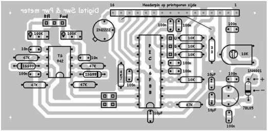
Figure 2- Board stuffing diagram.
While I ended up using this board I did modify the PAOEJH circuit slightly to align with both my experiences with linearized diode detectors, and to add in the ability to have an easy power/frequency calibration adjustment similar to the old Oskerblock style SWR meters.
My final circuit is shown in Figure 3.
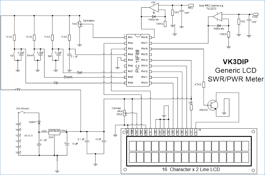
Figure 3- Meter schematic
Basically this easily fits on the existing board. Construction was simple, after making the PCB, basically following the stuffing diagram quickly had a working setup. I used a header and pins setup between the board and the LCD with only the various buttons, pot, and power switch being off board.
The only other bits required are a directional coupler, and some software (firmware) for the 16f88.
Based again on some earlier work I chose to use a classic “tandem match” style coupler the details for which are shown in Figure 4.
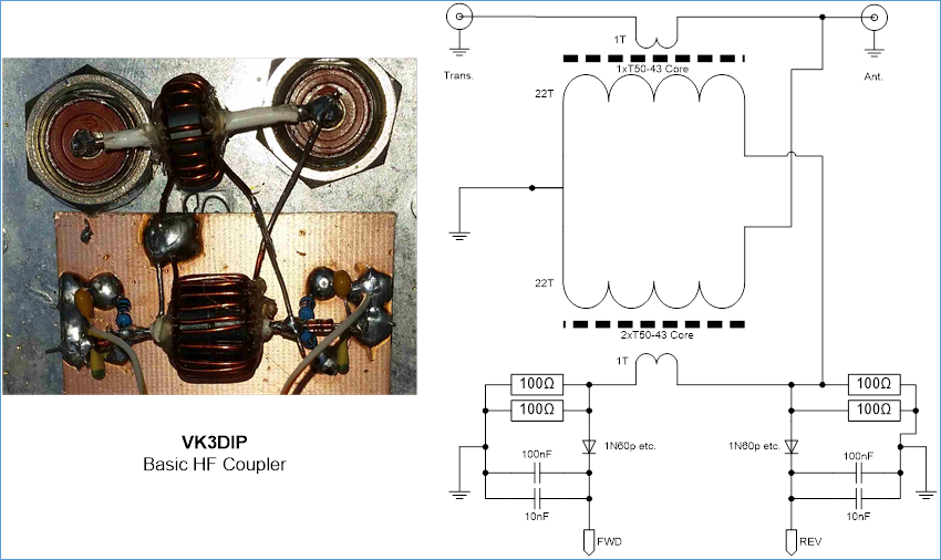
Figure 4- Directional Coupler.
The two main power determining factors here are the thermal dissipation in the cores, and the maximum rectified voltage out. The thermal dissipation ability gets better as the volume of ferrite increases, so normally large power implies large cores. The transformer effectively across the output is the critical one with respect to power handling, and as I had a number of smaller (T50-43) toroids (which are considerably cheaper than larger toroids) I ended up using two smaller cores taped together for this more critical transformer, to handle my expected 120W max. The voltage out in this meter design also has to be less than 5Vdc so as not to top out in the Op amps, With the 22 turns specified here I calculated that this design would have a coupling value of around 26.9dB and would thus produce (just) less than the 5V at the maximum 120 watts that I expect to measure. I will include the excel spread sheet I used to do these calculations on YagiCAD.com.
The construction was very straight forward. Basically the two transformers were mounted on the back of the diecast box that contained the rest of the meter. One transformer (the single core series or current transformer) is mounted with its primary between the two SO259 sockets mounted on the back. For the other transformer (the double core, critical shunt or voltage transformer), a small piece of PCB was bolted to the backof the box and small stands or props were made at appropriate distances apart using the 100Ohm resistors and the pair of capacitors. Hopefully you can see how this went in the above photo. Shielding is not necessary between the cores nor is electrostatic shields used in the primary windings. Theoretically shielding would help, but practically unless you can perfectly machine or manufacture the shields, even slight differences in spacing’s of the transformers to shields etc. will add uneven capacitances to deck which will likely lose you more in directivity than you might have otherwise gained.
The final required piece is the software. I originally thought that there were many versions of this available but on actually trying loading a few I found that there are all pretty much the same code, with binary edits to change the text of the various messages. I found versions in dutch and all sorts of non-English languages, but even the indian one from FoxDelta that purported to be in English turned out not to be. There was also the problem that there was no source for these codes just the compiled/modified hex, and there was very little documentation on how the code worked or in fact how to do calibration etc.
So, as I wanted to add the calibration pot thing anyway I decided to just write it myself from scratch. This ended up taking a bit longer than I thought, primarily because of the limited code size available in the 16f88, and while the PICSIMIDE Basic I used handled things like the floating point maths for me, it used up lots of space. Just doing the logarithm of a floating point number ended up filling the memory even before anything else. In the end after a number of tricks and shoehorning I managed to just fit (4092 bytes used out of 4096) the flow indicated in Figure 5.
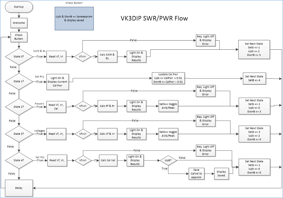
Figure 5- Program flow.
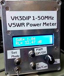
As can perhaps be seen the default state of the meter displays on the two lines of the display the SWR and (approximate, remember the log problem,) Return Loss in dB.
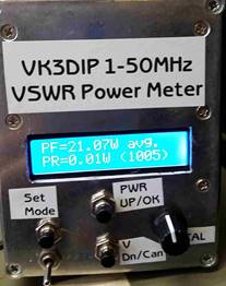
Pressing the Up button from SWR mode puts us into Power mode, and displays on the two lines power forward and reverse in watts and the current value of the calibrate pot. Basically the calibrate pot will show a value somewhere between 512 and 1538, with the centre value being nominally 1000. The way it works is there is an implied decimal point so the range of the calibrate is nominally between 0.512 and 1.538 with a nominal centre of 1.000. The meter calculates the power by multiplying the read count (either the average over 63 samples over about 1 second, or the peak sample over that same time, depending if average or peak is selected using the set button while in power mode) by a special value set and recalled from eeprom that converts the count to watts. This value will nominally only be truly correct at the one frequency you set it at, so the actual values displayed are the calculated value multiplied by the calibration factor. Say you set the meter at a standard value of 20Watts at say 28MHz. The power forward will then read 20watts for this power level at 28MHz (with cal pot at 1000 or 1.000 times) the idea is that at other frequencies you will have done a calibration curve that may say for example to get the correct reading at 14MHz the calibration pot may need to be set at 1010 ( 1.01 times). This way you can negate any frequency dependency of your particular coupler. With the basic setup here you can roughly calibrate out a range of 0.5 to 1.5 times the centre value. Pressing the up button again while in power mode will exit back to SWR mode.
Pressing the Set button in SWR mode starts the power base calibration process. To do the base set/calibration, you connect your transceiver to the meter input and a known good power meter (and termination) to the antenna port. You transmit a carrier on some convenient sub 100W power level (at a known frequency) and measure the actual power on the known good meter. Say the result is the transceiver is set for a nominal 20W, which the good meter measures at 21.1W. The initial screen in the calibration process on the digimeter shows the power set level (ie. the known power you are going to be transmitting) this starts off at 20watts and can be varied up or down using the up and down buttons in 0.01 watt increments to set the nominal level you will be transmitting at. So in the example here we would press up some 11 times to make the display 21.1W. Once the set value agrees with the reading on the known good meter, the set button is pressed again, and the display will now indicate this value and the actual count of the A/D that this corresponds to. At this point pressing the up button will save this count to watt calibration value, and pressing the down button will cancel the set/calibration process without saving. Once saved this value will be remembered even with the power off, and will only change if you go through the set/calibration process again. During the set calibration process the position or value of the calibrate pot has no effect.
As explained above this value set in the calibration process effectively sets the power accuracy at one frequency and one point where the calibration pot is set at 1000. To do accurate measurements at different frequencies you need to do another series of calibration checks at those different frequencies, this is done after you have done the set/calibrate above. The test setup is the same as for the set/calibrate but this time the digimeter is left in the normal power measurement mode. One then transmits at some nominal power level and adjusts the celibate pot until the reading on the digimeter is the same as on the known good meter. The various values of the calibrate pot verses frequency are recorded (and perhaps plotted on a graph). Once you have this graph you can quickly set the meter to give accurate power readings at the frequency of interest by just reading off the necessary calibrate value and setting it accordingly.
The final mode is voltage mode. This is entered from SWR mode by pressing the down button (a subsequent down press will exit back to SWR). In this mode the effective voltage measured forward and reverse is displayed.
You will note that if at any time no power is detected (or rev. is greater than fwd. meaning you have the TRANS and ANT connections back-to-front) the meter displays a bad values, check connections message. After a minute or so of this state the backlight will be turned off to save power. The backlight will come back on as soon as the correct (non-zero) levels of power are applied.
I will place the source and hex file for the digimeter on YagiCAD.com for any who want to do their own mods or just to duplicate my prototype.
73 Paul VK3DIP.
Back
Home