By Paul McMahon VK3DIP
At a recent NERG meeting I showed off several Return Loss Bridges I had made plus gave a demonstration on some of the things you could do with a RLB. One of these bridges was made by converting a three way splitter obtained at a Ham fest and looks and performs very much like a commercial RLB. As a number of people were interested in how this conversion was done, in particular my Brother-in-Law Charles Edmonds VK3CLE who supplied the splitter and who has more of them to sell at his usual Ham fest table, I have documented the process here.
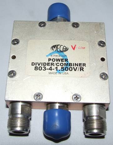
This is the splitter to be converted.
It is a small square of solid metal with a cavity milled out in it containing a Teflon printed circuit board with a series of microstrip lines and surface mount resistors forming the broadband Wilkinson divider networks. In its original state it is capable of splitting one signal (somewhere between 500MHz and 2.3GHz) into three or if used the other way around combining the signals from three inputs into a single output. If you happen to be doing things at this frequency this is a nice unit with good quality N type connectors and a very solid feel. If you don’t happen to be doing anything in this frequency range it is still a nice box and connectors and as shown below can be made into a very nice Return Loss Bridge.
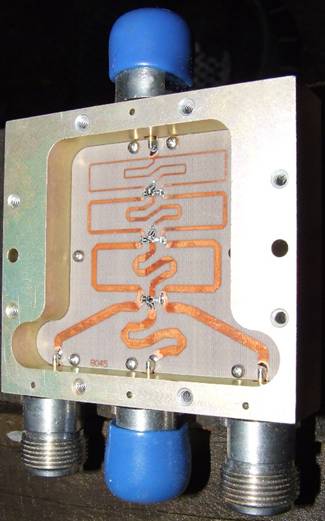
One of the nice things about this conversion is that the final sections of splitter microstrip going to the three output connectors seem to be at least near to 50 ohm impedance. So we can reuse the original board after making a few modifications to it. To do this we need to take it out of the box.
The thin Teflon board is held down by a number of screws and the connectors soldered to it, both things must be removed. The simplest way I found to remove the connectors is to first use an appropriate sized open spanner on the slots on the connector body to unscrew the metal barrel part of the connector leaving the inner pin and surrounding insulator still soldered to the board. These can be now simply removed with careful use of a soldering iron. Make sure you put the removed screws somewhere safely as you will need them to replace the board after modification.
 Unmodified
board.
Unmodified
board.
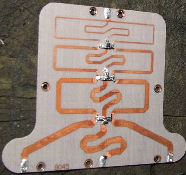
The board can now be modified by unsoldering the existing resistors, and then carefully cutting and removing the unwanted sections of the Microstrip. The object is to retain the three fattest sections of track as well as the pads that the N connectors solder to.
 Resistors
and tracks mostly removed.
Resistors
and tracks mostly removed.
The simplest way I found to remove the unwanted copper tracks was to use a small hobby knife with a flat ended blade like a mini scraper. You don’t really need to remove all the unwanted tracks you can leave the middle bit there as shown in the photo so long as there is no connections left to it.
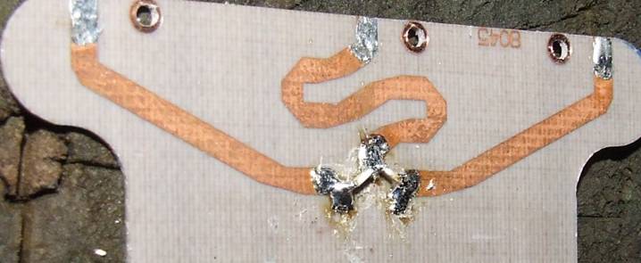
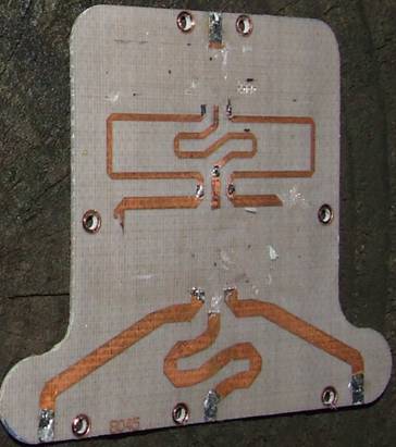
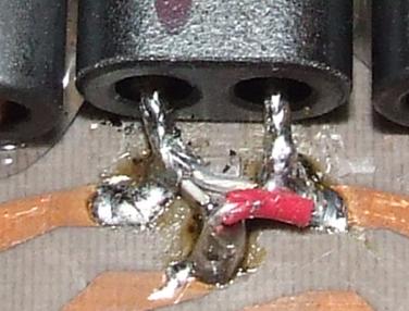
The next step is to solder on the new resistors that form the top arms of the bridge. In my case in the above picture I used 49.9 Ohm 1% 0805 size resistors obtained from Rockby Electronics mounted on there side to minimise capacitance. The resistors go from the common point which will be connected to the centre N connector and will become the generator input, with one each going to the arms on either side. If you don’t have the 49.9 Ohm resistors then you could also use two pairs of similar sized 100 Ohm resistors in parallel. 1206 size resistors probably wouldn’t make a difference and would be a bit easier to handle but I used what I had on hand in this case.
The final modification required before replacing the board in the box is to provide earth connection points for the coax braid at what will be the detector end of the board. For this you need some thin brass or copper sheet which is wrapped over the edge of the board near the two small screw holes. See picture below. This doesn’t need to be soldered to the underside of the board as it will be held in contact by the two screws.
The board can now be reinstalled in the box, screwed down and N connectors carefully resoldered.
For the Balun you need six 14 mm ferrite balun cores either ferrite type 43 (Rockby and others) or type M7 (Jaycar), or a mix. The 43 will provide better performance at lower frequencies the M7 is nominally better higher. You also need two 20cm lengths of RG178 or equivalent thin Teflon coax (Minikits and others).
Prepare the coax by striping the outer cover off each end for about one cm. The exposed braid is then tinned. On one length of coax the outer braid is lightly scored about halfway down each end with a pair of wire cutters similarly to ringbarking a tree. These ends can then be gently belt and the tinned braid should cleanly break and the end bits be removed leaving the inner conductor and its sheath untouched. This exposed inner can now be stripped about halfway down each exposed length and the inner conductor tinned. If you have successfully done this to each end of one bit of the coax you can just now shorten the second piece of coax to be the same length as the now outer braid of the first. The reason for doing this second is in case you slip when making the first one and accidentally say cut of the inner conductor when stripping it. In this case you have another chance to get it right with the second piece and the second bit with the mistake can be used as the compensating winding.
The ferrite cores are separated into pairs, ideally you would sort the cores based on test inductance of a couple of turns into as close to equal as possible but in practice this doesn’t seem to make that much difference. I join each of the pairs with some clear “sticky-tape” to make keeping the pairs together easier. The balun is wired as shown below.
The coax passes through the centre core pair once and twice through the outer cores. If you only have the slightly thicker RG316 or RG174 then you could try only a single pass through each hole of the outer cores.
The coax is terminated on the board at the three connector end as shown in the following diagram.
And at the single connector end as:
Note. this is not a particularly good terminating technique and it does make this port have the highest return loss of the lot but the RLB does still work ok. I am still playing with this trying to come up with a better method but the amount of available space is very limited.
When all wired up I use hot melt glue to secure the cores in place.
The RLB is now basically complete it can be connected up as shown below and tested for directivity etc.
All of the conversions I have done have basically worked very well with directivities of 40-50db at least up to a couple of hundred MHz without any further tweaking. If however you want performance at GHz frequencies then a small amount of tweaking may be necessary. Basically exactly what needs tweaking depends on the particular conversion but one technique that I have found to be useful is to solder one end of a small (7-8mm) piece of solid core wire to the common point between the two resistors and then to just bend it around with an insulated tool until I find a spot that achieves the required result.
Note. Leave the insulation on the wire so as not to short anything out.
After tweaking the sort of performance possible is very good as can be seen in the following sweep of directivity from 10MHz to 5 GHz.
This shows directivity better than 50dB to 500MHz, under 40dB to 1GHz, under 30dB to 2.5GHz, and just under 20db at 5GHz.