Versatile Microwave LO and Mixer Combo
By Paul McMahon VK3DIP
As appeared in NERG NEWS April 2021
Back
Home
Source Etc.
PC Board Artwork in Sprint Layout Format
This is basically an extension of the simple Microwave LO from November 2020 NERG News. As the 2.4GHz transverter rebuild nears completion I found myself in need of a signal source to test the receiver. I have a good signal generator but unfortunately it tops out at 1.35GHz which just isn’t enough for the 2.4GHz transvertor.
I initially tried this small bare board module which is quite useful for many things in that it produces a good signal from 35MHz to 4GHz, push button frequency entry, LCD display, and can be bought for around $20 on ebay etc.
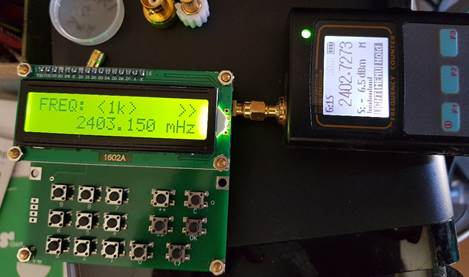
However, as a test signal source for transverter testing it has two big drawbacks. Firstly as you can see on the attached frequency meter, the onboard crystal reference is not very accurate, approximately 450KHz off at 2.4GHz , and secondly there is no level control, again from the meter (-6.5dBm) is quite a strong received signal, and you would need nearly 100dB of attenuation to get the level down to somewhere like weak signal levels.
Also finding, and or making an accurate attenuator of that level at 2.4GHz is quite difficult.
So I wanted another solution, luckily the work on the LO for the transverter suggested one and the SigMixGigs was born. Basically the idea is to mix the output of my existing siggen with a LO of some GHz from a ADF4350 PLL as an upconverter and thus to get an output that is frequency accurate, and with adjustable levels out down to my siggen floor level less the 8dB or so mixer conversion loss. Because the mixer output will be linearly proportional to the IF input level, if I go 20dB down in level on the siggen, the output from the mixer will go down by 20dB also.
The schematic for this is shown below.
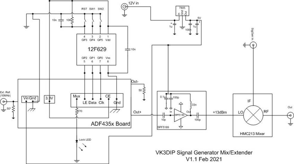
Details of the ADF4350 board, the PIC programmer, and buffer amp can be found in the previous Nerg news (Nov 2020). The only differences are different frequencies and levels set in the controller, and the addition of a small board with a broadband (HMC213) mixer on it. This mixer board can be found on the usual places (Ebay/Aliexpress) for $3-5 and comes with three SMA connectors.
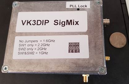
The inside of the SigMix is shown below.
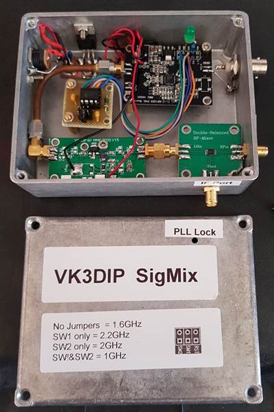
From top left approximately 12V DC is feed in to a three terminal 5V regulator which powers the ADF4350 (top right) and SPF5189 board (bottom left), as last time the programmer board (mid left) is powered from the on ADF4350 board 3.3V regulator. Bottom right is the mixer board with SMA connectors for the RF and IF ports protruding from the box. The BNC connector top right is to feed the external 10MHz reference from a GPSDO etc. to lock the frequency accurately. The green lock LED is placed in a small hole on the lid of the case.
Things to note:
1. The mixer for best frequency range requires approximately +13dBm of LO drive so the output from the ADF4350 is increased and the buffer is driven harder so it is bolted to the case via a standoff to act as a bit of a heatsink.
2. I used a male PCB mount SMA on the buffer output to simplify connection to the mixer LO port.
3. I used the alternate ADF4350 board from the Nov. 2020 one, which comes with a 25Mhz onboard osc which I removed. You could leave it on and not equip the external reference, but you would have to modify the control program accordingly. Also the frequency out wouldn’t be as accurate.
4. One other difference between this ADF4350 board and the last one is that this one did not have the 50 (49.9) ohm load resistor fitted at the reference input port, so I added it on the vacant PCB pads. If I had left it unfitted the 10MHz reference drive level required would have been much less but I like to have a standard input impedance.
5. The LO frequencies I chose (as shown on the front label) are 1.6GHz and 2.2GHz . As there is no filtering on the mixer output we get equal level output on the desired LO + IF frequency and undesired LO – IF frequency . This is not a problem for receiver testing so long as the unwanted mixer product ( and any harmonics of the LO) are as far away as possible from the desired one. So 1.6GHz LO with 800MHz IF input from the Siggen gives 2.4GHz (LO+IF) and 800MHz (LO-IF) and 3.2GHz ( 2xLO) . Both the unwanted outputs are 800MHz away from were the receiver is listening and don’t cause me any problems. Similarly 1.2GHz on the Siggen (IF) and LO of 2.2 GHz gets me ready for the 3.4GHz transverter coming up next.
In conclusion the sig gen mixer works very well, effectively extending my existing SigGen up to the 2.4 and 23.4 GHz amateur bands. The ouput on the spectrum analyser is clean (apart from the expected images mention before) and very linear in level.
As a side note because there are no filters here this setup can be used as a downconverter also, ie. say RF in from an antenna on the RF port giving you say a lower frequency output from the IF port to a receiver. In fact this could be the basis of a very simple transverter itself. Perhaps getting your 2M box onto the microwave bands. Probably this would be perfect for foxhunting, or just listening to higher microwave activity via your SDR dongle. The receiver without a preamp etc. would be a little deaf but it would work.
73 Paul VK3DIP.
Back
Home