A 4nec2 Model for a Linked Inverted V Dipole
Paul McMahon VK3DIP
After reading Tony’s write-up on his portable linked inverted V dipole ( April 2017 Nerg News) I was motivated to see if I could do a workable model for the antenna in a general purpose antenna modelling package, for me the best choice for this is 4nec2, it is free, and has many features even the paid for packages don’t offer.
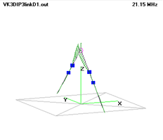
The setup for the antenna I ended up with is shown in Figure 1
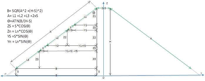
1 Antenna geometry
Basically the antenna wire is the green lines everything else is just to illustrate the maths to get a model that would automatically adapt to variations in centre height, and individual lengths of the three segments.
You can see from the above that I ended up adding a number of short wire segments to make the positioning of both the feed and link equivalents. In Tony’s original design the links used repurposed plastic chain insulators, and flying clip leads. In my model’s case the links are modelled as the short segments of wire which either have zero resistance, the equivalent of clip lead connected, and a high resistance (nominally 1 MΩ) , equivalent of clip lead disconnected.
The base model I ended up with (in 4nec2 .nec format) is shown below in Table 1.
1- Base Link Dipole Model
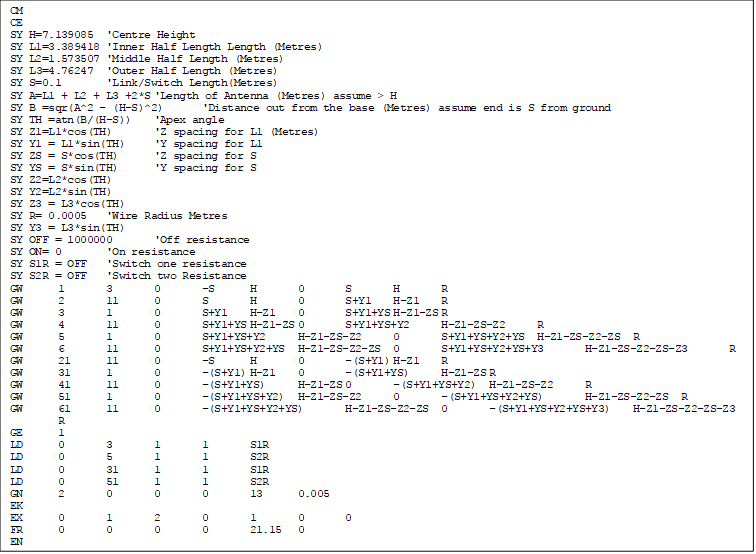
As can be seen I have made heavy use of 4nec2’s symbolic variable feature.
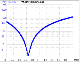
The first and simplest thing we can do with the model is use the 4nec2 optimizer dialogs to tweak things like the height and individual segment lengths. In my case I had started with a centre height of 10M, optimizing this for best VSWR showed that a centre height of around 7M actually worked better. I also optimized the individual radiating segment lengths centering them on the frequencies that I wanted. In my case I used 21.125MHz, 14.2MHz, and 7.1MHz.
If we were just physically building this antenna and tuning and testing physically then this would be about as far as you would go. It probably would have taken many hours of activity, raising and lowering the antenna, pruning off small lengths of wire, and retesting etc. No wonder Tony in his original article noted that he felt he could have got his prototype working better but it was too much effort. With the model however we can get to this stage very quickly, and even have the possibility to go further and look at other effects and variants.
One of the first extra things I looked at was the effect of different wire type and coverings. This can be seen in Table 2.
2 - Effects of real wire.
F MHz | Item | Ideal | (Copper/plastic) | |
VK3DIP3linkD1 | VK3DIP3linkD2 | %Variance | ||
21.125 | L1 | 3.3894 | 3.253 | 95.98% |
14.2 | L2 | 1.5735 | 1.5212 | 96.68% |
7.1 | L3 | 4.7625 | 4.6305 | 97.23% |
Typically the various rules of thumb presented in antenna handbooks etc. would have led us to expect that plastic coated wire would end up with shorter wire lengths. In this case for the arbitrary plastic and diameter I modelled we can see agreement with the shortening effect varying from around 4% at the highest frequency to about 3% at the lowest.
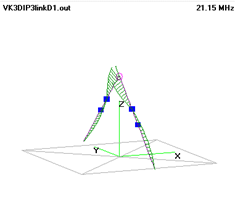
The next thing I looked at was the effect of not opening all links for the 21MHz case. As I expected if only the inner links were removed, the length of the resultant outer sections are also close to resonance at 21MHz, and do effect the antenna performance. The currents flowing in the outer section can be clearly seen in Figure 2 b. even though there is no direct electrical connection.
2 a. Left all links open, b. outer link still closed. |
|
The effects of not opening all links is to make the VSWR worse, change the overall resonant frequency (moving it out of the Australian ham band), and knocks nearly 2dB off the maximum gain. All just because of an accidental resonance.
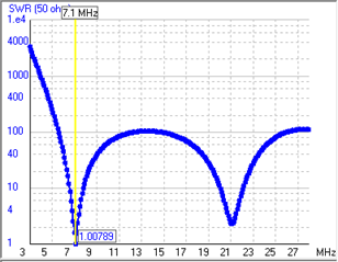
The model also enabled me to look at could we make the same antenna resonant at 3.6MHz by connecting in loading coils at the outer links. The model shows the following if the outer switch is replaced with a 35uH coil. (Figure 3)
3 Effect of a 35uH coil.
More so if we sweep over a wider range we can see that the resultant antenna is also resonant (still resonant) at 14.1 MHz. (Figure 4
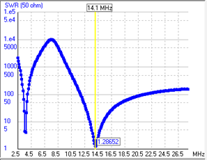
4 - 35uH also works as a choke and so antenna still works at 14.1 MHz
This effect sees the largish 80M loading coil acting more like a choke at the higher 20M frequency. The choke effectively acts like the (open) switch in the original design. So you could put the coil(s) in and have an antenna that works on 14.1 and 3.6MHz with no switches, one switch on the inner side would give us 21 MHz, and the outer switch shorting out the coil would give us 7.1MHz!
As another trick what about if we wanted to add 30M (10.1 MHz)? Again we can do that without changing segment lengths, just by this time replacing the Inductor in the outer switch positions with a capacitor. In this case adding a 13.7pF capacitor gives the following result. (Figure 5 )
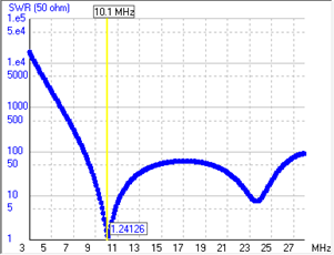
5- 30M capacitive loading.
As a final trick the thought occurred to replace the outer switch(s) with a pair of variable capacitors. When this is done we can effectively have an antenna that is continuously tuneable (by just turning a variable knob(s)) from 10MHz (or possibly even higher) at a value of around 13pF down to the nominal 7.1MHz at a C value of 252pF ( Figure 6)
6 - Increasing value of C.
I will place this info and an electronic version of the base model and some of the above extra’s on Yagicad.com in the Pauls projects area.
73 Paul McMahon VK3DIP.