A Miniature VSWR Meter for QRP Portable Use
Back
Home
Paul McMahon VK3DIP
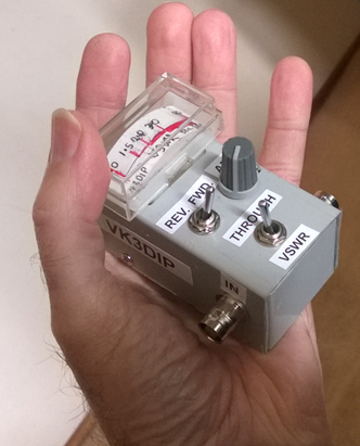
Figure 1 The MINIVSWR
As seen in Figure 1 this VSWR Meter is very small. The idea was to make something that could be taken out portable and used with something like the FT817 when playing SOTA or similar.
The parts list shows the bits I used but in most cases these are not particularly critical, substitutes will probably work just as well, though most items should be readily available from places like Rockby Electronics, Jaycar, or eBay.
|
Parts List |
|
Retex Minibox No.3 40x35x75 (Rockby Electronics) |
|
BNC Panel mount sockets x 2 |
|
100Ω 0.5w Metal Film resistor x 6 |
|
1KΩ 0.5W Metal Film resistor x 1 |
|
10KΩ miniature potentiometer and knob |
|
DPDT switch, SPDT switch |
|
10nF ceramic x 2 |
|
1N60p or equiv. Germanium signal diode. |
|
Small meter movement, in the prototype marked LDY5. |
|
Resistors/Calibration loads , 50Ω= 1:1, 75Ω=1.5:1, 100Ω=2:1, 150Ω = 3:1, etc. |
The particular box was chosen as being, small, metal, cheap, and just the right width to have the two BNC panel mount sockets just touch the through switch without any extra wiring. You should be able to see this, and how the other components fitted from the inside view in Figure 2.
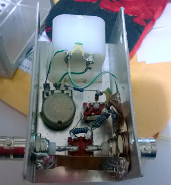
Figure 2 MINIVSWR Inside
The schematic of the MINIVSWR is shown in Figure 3
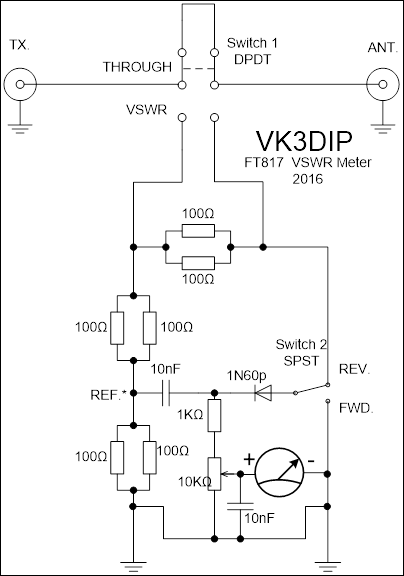
Figure 3 MINIVSWR Schematic
This is a simple resistive bridge VSWR meter. Which has several advantages:
1. Very wideband, the prototype works accurately from 1.8MHz through 52MHz, with reducing accuracy through 146MHz and 439MHz. At 146MHz the VSWR reads slightly low, ie. a 2:1 load will read as just between 1.5:1 and 2:1, at 439MHz this worsens with a 3:1 load showing up as closer to 2:1. In both cases however infinite and 1:1 VSWR loads are correct, so it will at least tell you if the antenna is good or not.
2. Simple calibration, no coils to wind, nor capacitors to trim.
3. Worst case VSWR as seen by the Transceiver is 2:1 even when used into an open or short, this will protect the Transceiver is you are taking a while to get the antenna match just so.
4. No external power needed.
5. Works with very low power levels, ie. Still sets with 500mW.
There are however some matching disadvantages:
1. You cannot leave the unit in line under normal working conditions, as there will be both TX and RX losses. Thus the Through/VSWR switch.
2. The resistors in the meter dissipate power, thus there is a limit to how much power you can apply to the meter. With the components here I wouldn’t use more than 2W while measuring.
Resistive VSWR bridges work similarly to all other VSWR bridges. Two voltages (in this case DC peak voltages representing the AC values) are measured which are proportional to the forward power and reverse power. Complex maths can be then done to these two voltages to give the VSWR. But typically as is the case here, a measurement is done in two stages; firstly the forward voltage is adjusted to give (just) full scale deflection on the meter; secondly the reading of the reverse voltage (which will be always less than the forward on the same range) can be then simply calibrated to directly read VSWR.
The only tricky thing with the circuit used here is the way the two voltages forward and reverse are measured. Strictly the voltage proportional to forward power is measured across the resistors from the reference point (ref. in the schematic) to ground, and the reverse is measured between the reference point and the top of the load. So properly the meter should have one side connected to the reference point. This would however require a suitably wideband RF choke to pass the DC without affecting the RF, so in the case here we use the fact that the resistors from the reference point to earth can also pass DC and the value of 50Ω is small compared to the other resistors used (1KΩ and 10KΩ), and gets lost in the calibration.
The diode I used is a Germanium one. I chose this type specifically because it has a lower conduction point (Vf ~300mV)) than both normal Silicon (Vf~700mV) or Schottky (Vf~500mV). Below this point the diode behaviour becomes non-linear and the effect in the VSWR meter case is to under estimate the voltage. So a Germanium diode gives the best low power response.
Construction is straight forward basically mount all the components in the “U” shaped half of the box, and then the resistors etc. basically go from terminal to terminal of the various switches etc.
I placed a small piece of copper under the input BNC connector to form a common ground point that can be soldered to. You would also notice from Figure 2 that I soldered another spall piece of copper shim between the two earth lugs of the BNC’s just to be sure of a low impedance connection there. Obscured in this photo the bottom two lugs of the Through/VSWR switch are bridged with yet another small piece of copper.
Calibration of the meter scale is done with the cover off the meter movement. Then the two points corresponding to the two end stops are made which will form the 1:1 and Set/Infinite VSWR points. The 1.5:1 point is marked after connecting a 75Ω load (75Ω resistor in a BNC plug) and doing the set procedure. I did all calibration at 28MHz, but you can use whatever frequency you are most interested in as there will be small differences, if however you use above 50MHz, as noted before, this will lead to inaccuracies at the lower frequencies. A similar set with 100Ω and 150Ω loads will give you the 2:1 and 3:1 points respectively. You can mark other points if you require them (VSWR = VSWR x 50Ω) but I found these five points enough for my purposes. Note you must redo the set adjust with each load as there will be slight differences in the forward power with each instance.
73 Paul VK3DIP
Back
Home