EX 27Mhz CB SWR meter Rebuilds
Back
Home
Paul McMahon VK3DIP
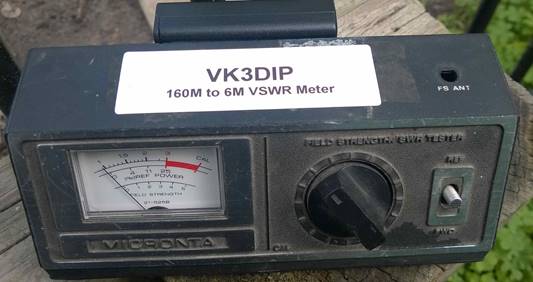
This article briefly describes a couple of my attempts to turn old 27MHz CB SWR meters of unknown specifications into at least known accuracy measurement instruments. The base meters were bought for $5 - $10 in unknown state at various hamfests and they all have the same basic design. The design dates back to the venerable “Monimatch, Mark II” as described by Lewis McCoy in February 1957 QST, and the even earlier Monimatch from October 1956. The setup is more or less as shown in Figure 1. It has three main parts; the Directional coupler, the Detectors, and the Metering circuit.
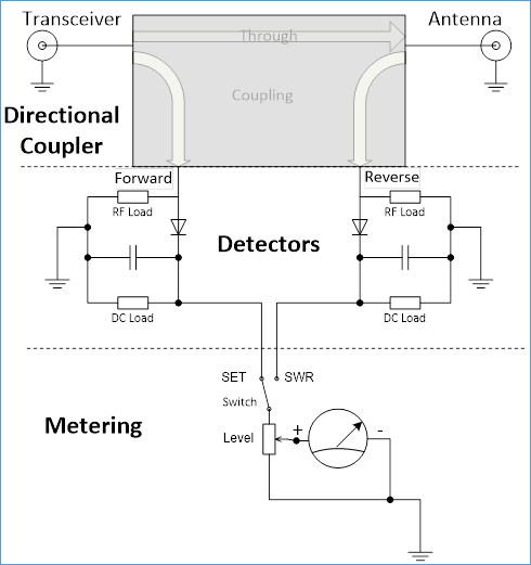
Figure 1 - Basic SWR meter design.
In the Monimatch style devices, which as I said is the case for 99% of the 27MHz CB meters you will find, the Directional coupler is usually a coupled line type with a main through line with two closely spaced sampling lines next to it. This type of coupler can be made very cheaply, and can be fabricated in practice using either discrete wires or an etched PCB. The etched type is shown in Figure 2.
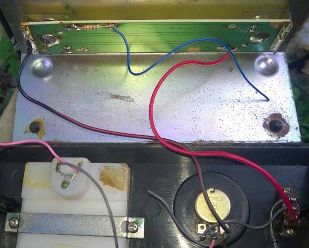
Figure 2- "Monimatch" style coupler in one of the donor meters
There are a large number of other styles of couplers that can be used with many different features. Typical commercial ham devices use a “lumped” element design with a single transformer “Bruene”, or “Douma” style circuits. The homemade ones tend to be a dual transformer “Tandem Match” or “Stockton” style. I tried using one of each for the examples here.
The metering component is very simple, usually just a typically 10KΩ potentiometer to set the level and a sensitive (typically 50μA - 150μA) meter calibrated according to :
![]()
By setting the level of the Vfwd component (with switch in set position) using the potentiometer to full scale this equation reduces to:
![]()
This gives the classic scale on the meter you will see and with the switch in the SWR position allow you to read of the SWR.
This is all very simple, and if all you want is a meter that is correct for a particular pretty much fixed frequency and power level, then you can even make it accurate by playing with the meter scale a bit to allow for the diode non-linearity’s. Typically, if the standard scale is used it will tend to under estimate the SWR, so sometimes in nominally more accurate meters you would see the scale played with a bit at the low end. For 27MHz CB the frequency range is quite small and the power level was theoretically fixed so you could tweak the design a bit to include somewhat lower coupling values of 6-10dB and higher values for the RF terminating resistors. All targeted at getting the values for the peak voltages especially for Vrev. as high as possible.
Why you want to do this can be seen from Figure 3. Where I measured some typical diode detectors.
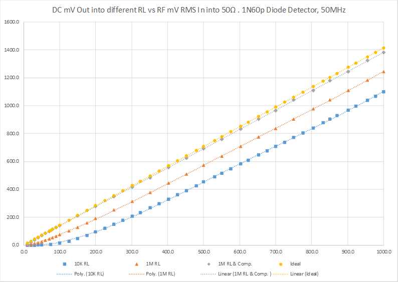
Figure 3 - Diode detector response
The blue line with the squares shows the DC millivolts out
(Peak) for various values of RF (RMS) millivolts in. In this particular case
using a reasonably good Schottky diode for the detector, into the typical 10
KΩ load of the normal metering circuit. The yellow line with the circles
shows the response of an ideal diode detector where ![]() . You can see two important effects;
firstly, the detected voltage will always be at least 200 – 400mV low;
secondly, that below about 300mV RMS IN the output becomes very nonlinear. All
this means that the SWR value you get from the above equation is never going to
be exactly correct and especially at values of SWR getting down closer to 1,
where the reverse voltage is much less than the forward value, and even more
especially where the power through the meter is low, the divergence from the
theoretical values will be worst.
. You can see two important effects;
firstly, the detected voltage will always be at least 200 – 400mV low;
secondly, that below about 300mV RMS IN the output becomes very nonlinear. All
this means that the SWR value you get from the above equation is never going to
be exactly correct and especially at values of SWR getting down closer to 1,
where the reverse voltage is much less than the forward value, and even more
especially where the power through the meter is low, the divergence from the
theoretical values will be worst.
Typically, with coupling values of around 20-30dB even with 100 watts in the through path the forward voltage will only be some 4 volts, and you need to have the SWR greater than about 1.2 before you get the reverse voltage above the diode knee. At 10 Watts this point occurs at closer to 2:1. Bottom line you can change the meter scale to have so 10% error but it will only be at or above a certain power level. If the coupler is in anyway frequency dependant (as is the Monomatch) this will also only be at one frequency also.
Figure 3. Does also give pointers to how to reduce the errors, as you can see from the orange line with the triangular marks, increasing the DC load resistance to 1MΩ pretty much halves the offset etc. In a passive meter this sort of input resistance is more or less impractical. So you need some sort of buffer amplifier to achieve this sort of value. Which brings us to the grey Diamond shaped marker curve. To obtain this curve I used a circuit popularised as a part of the original “Tandem Match” design by John Grebenkemper as published in January 1987 QST and appearing in pretty much every ARRL handbook since. The version I used for these tests and in the rebuilt meters is shown in Figure 4.
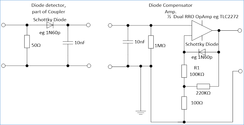
Figure 4- Grebenkemper Circuit QEX August 1990
The idea here is to include a diode matched to the detector one in the feedback loop of the op amp. If the voltage into the buffer is less than the full turn on voltage of the diode, the diode naturally conducts less well and as it is in the negative feedback loop this effectively increases the op amp gain correspondingly increasing the output from the buffer. The 100 and 220KΩ resistors just set the maximum level of the gain to prevent things like the op amp offset input voltage skewing things. In effect you end up with an amplifier with the reverse characteristic to that of the diode by itself. Use both and you get a linear response as shown by the grey curve. This is very close to the ideal diode response.
So to rebuild my meters, as I was doing a few of them at the same time, I designed a small PCB to accommodate this circuit. See Figure 5. As this is all at DC you could use vero-board or any other sort of proto-board if you wanted to. The one dual op amp handles two buffers so you can buffer both forward and reverse voltages at the same time, in one small package. I used 1N60p diodes because they are very cheap on ebay (a couple of $ for 50 pieces) and in that number it is very easy to find a number of matching pairs (using the diode forward voltage test on your multimeter). Also these are actually quite good diodes being a (very much mass produced) Chinese schottky diode produced as a replacement for the earlier 1N60 germanium part. Typical claimed specs are a peak reverse voltage of some 45 volts, and a capacitance of some 6 pF, which along with typical schottky linearity make it a better choice than the ubiquitous 1N34 germanium diode used in many US designs. Also some words on the opamp, I used a TLC2272, which is a cmos rail to rail output with input dynamic range including negative rail. Al this basically means it uses low quiescent current, and on a single supply say a 6 V battery the input can go down to zero volts and the output can go from 0 to the full 6 volts. If you wanted to duplicate this sort of thing, then either use a TLC2272 or one of the many equivalent so called RRO opamps. If you are going to run this of say a 12V mains supply, then you could get away with using a very much cheaper LM358 or equivalent. These are not rail to rail output devices and can typically not get to closer than some couple of volts of the positive supply on output. This would considerable limit the maximum power you could use in a battery powered situation.

Figure 5 - Diode buffer Mirrored, PCB full size.
The compensation board mounted inside the case of the smaller of the two meters is shown in Figure 6.
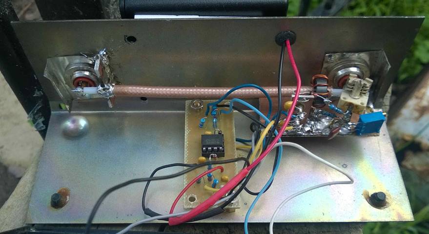
Figure 6 - board inside a meter.
You can also see in this case I used a single transformer coupler design, and the 4 AA cell battery pack (ie. 6V) with power switch is mounted using double side tape on the back of the box with power entering via a grommeted hole.
Figure 7. shows the inside of a somewhat larger 27MHz CB meter which had power scales as well as SWR. You will also see in this case I used a pair of trimers to vary the value of R1 as shown in Figure 4
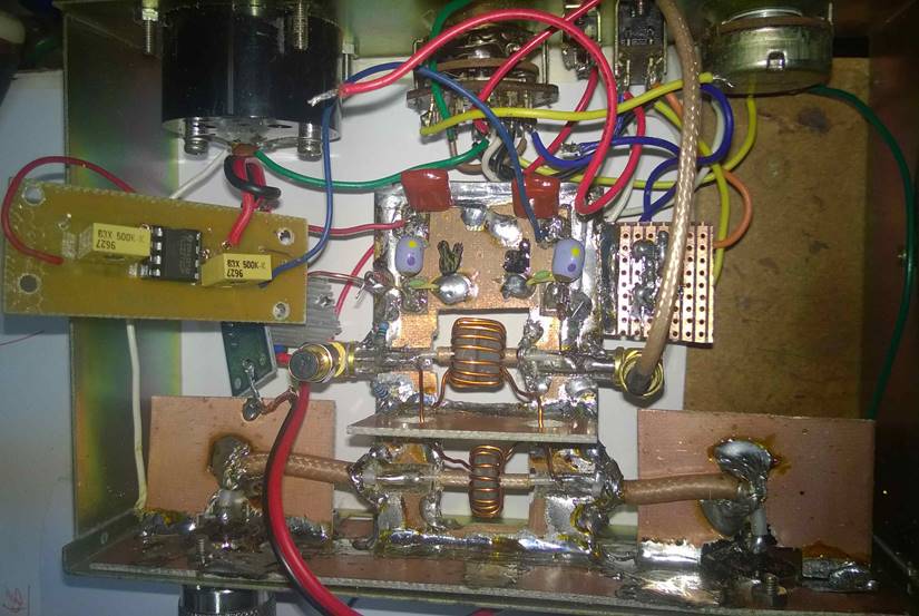
Figure 7 - Inside a larger rebuilt meter
In this case I found the optimum value of R1 was pretty broadly about 95KΩ (with schottky diode and 1MΩ DC load resistor), so in all the versions I have made since I just use a 100K fixed resistor.
Also in this case I used a two transformer style “Tandem Match” coupler. The use of two cores in the shunt (voltage) transformer is to provide both increased impedance at lower frequencies (ie. better at 1.8MHz) as well as to handle the power dissipation in this transformer at higher 100W power levels.
Both of these rebuilt meters give very good results being pretty much independent of frequency or power (greater than a couple of watts in). Both easily cover the range of 1.8 – 52MHz .
The Tandem match coupler didn’t require any tune up unlike the single transformer type to obtain best directivity. (basically tune for minimum swr when terminated with a good 50Ω load). However it did use two less T50-43 cores and required less toroid winding. Also the Tandem style does require careful design of the voltage transformer to ensure it can handle the required power.
Anyway for not much money I now have a couple of meters that I can have quite a bit of confidence in the numbers they give me.
73 Paul VK3DIP
Back
Home