Adding a Custom Element (a U-Bolt) to YagiCAD 6.3.X
By Paul McMahon VK3DIP
Back
Home
Source Etc.
Example Elemlib.ycl and library doco file
You certainly don’t have to be able to add custom element types to YagiCAD to be able to fully use YagiCAD, however there are some circumstances where an advanced user could want to add something a little different to what is available off the shelf. In my example here I want to see what effect putting a U-Bolt in the boom between two other elements will have. This document is a brief overview of how to go about adding a new element type in the Elemlib.ycl file.
Firstly a warning there is relatively little in the way of error checking done by YagiCAD when it loads the elemlib file at startup (which is the only time it is loaded, so if you edit it , you have to stop and start YagiCAD to import any changes) so if you get something wrong straaaang things may happen.
In YagiCAD 6.3.0 and on, the element types are defined in a file called Elemlib.ycl which should be located in the same folder as the yagicad exe file. Elemlib.ycl is a simple text file that has a defined structure which can be edited with any standard text editor such as notepad etc. Before you make any changes I recommend you make a copy of the original first and rename it to say Elemlib.bak. If you manage to break something you may have to revert to this backup.
Assuming you have now opened Elimlib.ycl in your favourite text editor, I will use notepad in the examples here, the first thing in the file you will see is lots of comments (see Figure 1) . Anything after an ! character ( or ‘ if you prefer) is ignored by YagiCAD it is just there to provide explanations to humans who may be reading the file. The first real statement is NUMCELLS followed by a number, 16 in the example here. This tells YagiCAD that this file contains definitions for 16 element types which will be numbered 0 to 15. As we are adding one element type in this example the 16 is changed to 17, and it will be element 16 that I will be adding. This can be confusing to some but it is just because the element numbers in YagiCAD start from 0 , ie. the first element is element 0, the second element is element 1, and so on.

Figure 1- Start of Elemlib.ycl in notepad.
As you scroll through the file to the end (after changing the 16 to 17) you will notice there is a section for each element type definition. These sections start with an ELEMENT <space> “n” line and end with a corresponding ENDELEMENT <space> “n” line. The “n” should match in each case as they are the element number as will be known by YagiCAD. In this example I am adding what will be element 16, so down at the end of the file (after the ENDELEMENT 15 line) on a line by itself we add in ELEMENT 16. Note there must be at least a single space between the ELEMENT and the 16 , multiple spaces will be treated as one , and blank lines will be ignored. You can make any comments you want using the ! etc. but be aware everything on a line after the ! will be ignored by YagiCAD.
You can put in the ENDELEMENT 16 statement as well on a new line if you like , and insert the other statements in between, or just add it after you have finished the rest, but don’t forget.
The first YagiCAD readable statement after the ELEMENT “n” statement should be the ENAME statement. After the ENAM comes two parameters, the (short) name this element which be known as in YagiCAD, and the default value in wavelengths that the LENGTH variable will take when an element of this type is initialized. Throughout the element type definition file the space (one or more) character is used as a delimiter so individual parameters must have at least one space between them and can have no embedded spaces. So for our example here I will call the element type UBolt and arbitrarily set the LENGTH default to 0.1 , so the line becomes ENAME UBolt 0.1 . Note the spaces. In the case here I don’t really need to worry about what I set the default length to as this is more relevant if I am defining an element type that I want to scale with frequency, in my U-Bolt case 0.1 wavelengths is as good a start value as any. If however I was defining what I wanted to be say a resonant halfwave dipole I might have started it at 0.48 wavelengths. In my U-Bolt element type case I am going to define the LENGTH as being the distance from the end of the threaded ends to the peak of the V at the base of the “U” , and I will set it directly inside YagiCAD when I use it, depending on the actual U-Bolt I am trying to model. The Simple model I am going for is shown in Figure 2.
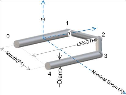
Figure 2- U-Bolt Model
The next statement in this new section will set the number of optional parameters that will be used by this element type. This can be 0 , 1, or 2, depending on how many of P1 and or P2 are used. In my example here I want to just use P1 to set the width of the mouth of the U-Bolt, so I will set OPTPARAMS to 1. Ie OPTPARAMS 1. The first non-commented line after OPTPARAMS contains the name that will be displayed at the top of the P1 column on the YagiCAD main page, and the default value for it again in wavelengths. I will call P1 Mouth in this case, and once again the default doesn’t really matter so again I will set it at 0.1. So these few lines will now contain:
OPTPARAMS 1
Mouth 0.1
The next/remaining statements define the element type in a manor similar to that used in a 4NEC2 .NEC file. Ie. they are effectively images of the relevant NEC card image statements that would be used to describe the element assuming you used symbolic statements similar to those used by 4NEC2. There are four sets of information. The first is the SYMBOLS that will be used in the other three sections that will respectively describe; the wire geometry (STRUCTURE) ; the individual wire conductance loading (LOSSES), if requested in YagiCAD ; and the excitation/control (SOURCE) required for the driven wire, again only if required.
Each symbol in the SYMBOL section consists of a label and an expression. The label starts with either a L, I, or F character depending on if the expression should be numerically evaluated as producing an Integer (I) , a Floating Point (F) , or should be not evaluated but directly interpreted as a Literal (L) string. At the moment after the first type character in the label must come a number starting at 0 incrementing by one for each symbol used. The number parameter after the SYMBOLS word gives the number of symbols that will be used in this definition. The expression parameter for a symbol can contain many standard mathematical functions such as + - * / ^ () ,as well as functions like; sqr(), sin(degs), cos(degs), tan(degs), log(), log10(), atn(), and exp(), there are also some special functions; ASEGS() which takes an argument in metres and returns the number of segments that are auto allocated based on what would be current values for segments per halfwave and frequency at the time of evaluation, and TAG which returns a suitable value for an initial identifying tag for this element. There are also several predefined values that come from the specific YagiCAD Yagi/element instance such as XCENT, YCENT, ZCENT, (the X, Y, and Z, reference co-ords for this Yagi typically 0,0,0 for a stand alone Yagi ), XOFFSET, LENGTH, DIAM, P1, P1, ECOND, the element position along the X axis, its length , diameter, values of optional parameters P1 and P2, all in metres, and the element material conductance. Finally there is a variable LAMBDA which is the current wavelength also in metres. All normal numbers are also possible. At this time expressions cannot reference other expressions/symbols. Literal versions can consist of any characters etc. Expressions can be as short as a single digit, or as long as can fit on a single line in your editor. Ie. it is the CRLF that determines the line not arbitrary numbers of characters.
As can be seen in Figure 2 this model element will consist of four wires with five endpoints 0-4 as in the diagram. For the Symbols I tend to follow a structure of defining those for the Tags first, then the segments required for the various wire lengths, then the X Y and Z co-ordinates of the wire ends, finally the other miscellaneous bits required to finish off the other statements. You don’t have to follow this order but I find it helps to organise my design and not forget bits.
So firstly there are four wires in this model so typically I would do the first four symbols defining those tags. Tags are used in the element type description (similarly to in NEC2 etc.) to identify particular wires and to associate them with sources or loads from the other sections. In this case, where for obvious reasons we only want this to be a passive element and not a driven, one we don’t need to have all wires have different Tags so we could just have all four wires have the same tag (TAG as allocated) but likewise there is no problem with giving each wire an individual tag. In YagiCAD 6.3.x Tags are basically an integer number that is structured to identify; the particular Yagi in a possibly larger array of Yagi’s, the element in that Yagi, and the wire within that element. Also indicated is the driven wire if applicable. A limitation of this tag structure is that no element can have more than nine uniquely identified wires. Note. It is possible to have many more than nine wires comprising one element, there must be multiple wires with the same tag in this case, there is no enforced limit to the number of wires in an element with the same Tag , however too large a number of wires will slow the NEC engine down and become impractical. The tag function will not allocate a Tag of 0 which has a special significance in NEC (its basically not able to be referred to). A feature of the tag structure means that the 9 possible unique tags for an element are sequential after the initial allocated TAG. In our case here of four wires with four tags that’s means we can use TAG, TAG+1, TAG+2, and TAG+3 . These Tags are integers so the first four symbols in this example would be:
I0 TAG
I1 TAG+1
I2 TAG+2
I3 TAG+3
The next symbols I would normally define belong to the number of segments needed in each of the wires, wishing to have these automatically allocated these will use the ASEGS() function and be dependant on the lengths of the individual wires. In this example there are only two different lengths of wire, the wire between point 0 and 1 (same as 3 to 4) and the wire from 1 to 2 (same as 2 to 3). As we can reuse each symbol as many times as required in the following definitions only two segs symbols are required. From geometry and Pythagoras the length of 0-1 is LENGTH-P1/2, and 1-2 is 0.7071*P1. Strictly speaking 1-2 is actually P1/sqr(2) which I could also have used, but the additional precision has no benefits to offset the (admittedly very small) additional time taken to evaluate the function. The number of segments is also an integer so the next two lines of symbols become:
I4 ASEGS(LENGTH-P1/2 )
I5 ASEGS(0.7071*P1)
In the next lot of symbols I normally define the various different values of X, Y, and Z co-ordinates needed to specify the, in this case 5, endpoints needed. All co-ordinates are typically floating point / decimal numbers. For endpoint 0 the X co-ord is simply the XCENT of the Yagi (by YagiCAD convention the rearmost elements X position), plus the XOFFSET value of this instance of this element (shown as spacing on main YagiCAD grid) ie. the symbol statement will be F6 XCENT+XOFFSET, remember the 6 is for the sequential numbering of the symbols. Similarly by the geometry of this example we need an additional two X symbols, three Y’s, and one Z. These symbols then become:
F6 XCENT+XOFFSET
F7 XCENT+XOFFSET+P1/2
F8 XCENT+XOFFSET+P1
F9 YCENT-LENGTH/2
F10 YCENT+LENGTH/2-P1/2
F11 YCENT+LENGTH/2
F12 ZCENT
Note as this UBolt is in the plane of the Yagi nominal boom the Z co-ordinate is constant.
Using these symbol values we could then see that the five wire endpoints indicated on the diagram above become:
! endn = X Y Z
End0 = F6 F9 F12
End1 = F6 F10 F12
End2 = F7 F11 F12
End3 = F8 F10 F12
End4 = F8 F9 F12
YagiCAD does not need these explicitly given in the element definition file but I would normally put them in as a comment just so that I can keep track of what I am doing.
The last symbols are some miscellaneous ones needed to complete the structure lines, such as the element radius F13 DIAM/2, and some simple literals and values to help with the losses and source bits. While I don’t need a source section in this case because, I see no reason I would ever want to have it driven I have left in some symbols that are only needed for the source line ( such as the literal EX ) just to illustrate that extra unused symbols in an element definition don’t matter, and also because I copied and pasted from one of the other definitions ( and re-did the symbol numbers).
! Other Bits
F13 DIAM/2
L14 EX
I15 0
I16 1
L17 LD
L18 5
F19 ECOND
So now I know I have defined 20 symbols in total ( 0-19) so I can ensure that the number parameter after the SYMBOLS keyword is 20 ie SYMBOLS 20.
The next section is the STRUCTURE one that will define the actual geometry of the element type. It starts with the STRUCTURE keyword with a single numeric parameter of the number of wires in the structure. In this example there are four wires so it will be STRUCTURE 4 .
The line/s after the STRUCTURE<space>n (one per wire) are basically in the same format as the NEC GW card without the GW, there are nine parameters for each wire; Tag Segs X1 Y1 Z1 X2 Y2 Z2 Rad. So for the first line which will define the wire between endpoint 0 and 1 we have: I0 I4 F6 F9 F12 F6 F10 F12 F13 . Note each parameter is made up of a single symbol this is the only possibility, ie. you cannot put in numbers or literals directly, or expressions involving symbols for that matter. So the four wires for this example would be:
STRUCTURE 4
! Tag Segs X1 Y1 Z1 X2 Y2 Z2 Rad
I0 I4 F6 F9 F12 F6 F10 F12 F13 ! End0 - End1
I1 I5 F6 F10 F12 F7 F11 F12 F13 ! End1 - End2
I2 I5 F7 F11 F12 F8 F10 F12 F13 ! End2 - End3
I3 I4 F8 F10 F12 F8 F9 F12 F13 ! End3 - End4
The next section is the LOSSES section, this typically contains images of what the NEC load type 5 card/s would look like. In this case where we just want to allow that we might want to try different materials for the U-Bolt we just have four losses lines (one per wire) each of six parameters, this time unlike the GW wire geometry case we must include the card label eg. the LD. So the classic format would be LD 5 Tag 0 Segs ECOND, which basically says to apply the conductance ECOND to the wire of Tag Tag, from segment 0 to the total number of segments in that wire segs. As with the other sections the number parameter after the LOSSES keyword is the number of lines of losses that follow, so the relevant lines in this case would be:
LOSSES 4
!LD 5 Tag 0 Segs ECOND
L17 L18 I0 I15 I4 F19
L17 L18 I1 I15 I5 F19
L17 L18 I2 I15 I5 F19
L17 L18 I3 I15 I4 F19
The final section before the ENDELEMENT is the SOURCE one. The items in the LOSSES section only get used if the conductance of an element instance is set in YagiCAD to non-zero. The items in the SOURCE section only get used if YagiCAD indicates the instance of this element type is driven. If however we never want this particular element type to be driven we can omit the source section entirely (or just set SOURCE 0 , ie. zero lines of source definition.) This is what I have done in this case here where we don’t want to be able to feed the U-Bolt. If we tried to set an instance of this element type as driven then YagiCAD, because there is no source info, would change the type back to the defalt type 0 (simple dipole). If we did however whant this to be drivable then as you will see from other element type definitions, typically only one of the wires would have a source in it, and this would typically be the wire identified with the root TAG symbol (ie. not the TAG+1 symbol etc.). The format for this simplest usual case is seven parameters EX 0 Tag midseg 0 1 0 , ie. again the card image included the card prefix EX. As you would see from other examples the symbol that defines midseg typically has an expression with the number of segments auto allocated for the entire length of the driven wire plus 1 all divided by 2 and expressed as an integer. This expression will always point to the middle segment in an odd number of segments in the NEC case and will work out equivalently for even pulses in the MiniNEC case. Nominally in both the LOSSES and SOURCE cases other card images could be included such as transmission lines (TL) and networks (NT) but that would only be necessary for very complex elements and there are no examples of this to date. So again in the example here the final lines of the definition file work out to be:
! SOURCE (only if Driven) section consists of 0 line
SOURCE 0
!EX 0 Tag midseg 0 1 0
! no source defined cannot be driven.
ENDELEMENT 16
And that is it, save the file and stop and start YagiCAD and there should be a new element type defined, which you can now use.
Not quite all, because if you intend to keep this new element definition longer term , and or want it to show up and not break the help element viewer you would also need to add it to the element library viewer definition file which can be found in the element browser folder called elib.txt. Again this is a simple text file that can be edited with notepad . In this file there are no comments etc. just four lines for each element type defined consisting of :
· The element number as known to YagiCAD.
· The Short Name as known to YagiCAD.
· A filename of an image file (jpg, png, etc.) that shows what your element looks like and where LENGTH is etc.
· And finally a line (potentially quite a long line, describing the element type in words.
If we were to do this for the UBolt case here these four lines added to the end of elib.txt could be:
16
UBolt
UBolt.jpg
Simple U-Bolt model Default length and P1(Mouth) = 0.1Lambda
In this example I would also have to place an image such as figure 2 above in a file called UBolt.png, and place it in the element browser folder.
73 Paul VK3DIP.
Back
Home